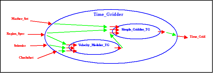
This topic extends the earlier examples to introduce a second workflow for creating a Velocity_Model, and incorporating this workflow together with Simple_Gridder in a composite, or super-workflow. The new concepts are hierarchy in the workflow, and the use of Act_Tmpl_Dataflow_Arcs to represent the internal plumbing connections between the various inputs and outputs of both the sub workflows, and between the sub workflows and the superworkflow.
Start by installing a new component called the Velocity_Modeler. Schematically, this might look like this:

Following are example entries in the Workflow (basic workflow definition) and Act_Tmpl_Data_Role (workflow inputs and outputs) tables, with assignments of the named data roles to supported data types:
|
Id |
Name |
Primary_Owning_Activity_Template_Id |
Filename_of_Executable |
Super_Workflow |
Activity_Subtype |
|
|
0021 |
Simple_Gridder |
Point_Gridder |
C:\progs\gridder |
NULL |
Generic_Activity |
|
|
0024 |
Another_Gridder |
Point_Gridder |
C:\progs\wazoo_grids |
NULL |
Generic_Activity |
|
|
0026 |
Velocity_Modeler |
Create_Velocity_Model |
C:\progs\velocity |
NULL |
Generic_Activity |
|
|
Role_Name |
Role_Type |
Entity_Type |
Min_Card |
Max_Card |
Activity_Template_Id |
|
Seismics |
Input |
Seismic_3D_Survey |
1 |
1 |
0026 |
|
Checkshot |
Input |
Well_Checkshot_Survey |
0 |
1 |
0026 |
|
Region_Spec |
Input |
Polyline |
1 |
1 |
0026 |
|
Depth_Conversion |
Output |
Velocity_Model |
1 |
1 |
0026 |
The new workflow can be activated in a way similar to the original Simple_Gridder example. An observation here is that the Velocity_Modeler program creates an instance of a data type that can serve as input to Simple_Gridder, for example, so that Simple_Gridder might create time-indexed grids, rather than the depth-indexing that results from gridding depth data. For convenience of use, a super workflow, Time_Gridder can be created that includes both workflows and defines some connectivity of data between them.

Note that copies of the Velocity_Modeler and Simple_Gridder workflows had to be created for use specifically in the new superworkflow. The resulting Workflow and Act_Tmpl_Data_Role tables look like this:
|
Id |
Name |
Primary_Owning_Activity_Template_Id |
Filename_of_Executable |
Super_Activity_Template_Id |
Activity_Subtype |
|
0026 |
Simple_Gridder_TG |
Point_Gridder |
C:\progs\gridder |
0028 {Time_Gridder} |
Generic_Activity |
|
0027 |
Velocity_Modeler_TG |
Create_Velocity_Model |
C:\progs\velocity |
0028 {Time_Gridder} |
Generic_Activity |
|
0028 |
Time_Gridder |
Point_Gridder_In_Time |
NULL |
NULL |
Generic_Activity |
|
Id |
Role_Name |
Role_Type |
Entity_Type |
Min_Card |
Max_Card |
Activity_Template_Id |
|
0401 |
Seismics |
Input |
Seismic_3D_Survey |
1 |
1 |
0027 {Velocity_Modeler_TG} |
|
0402 |
Checkshot |
Input |
Well_Checkshot_Survey |
0 |
1 |
0027 {Velocity_Modeler_TG} |
|
0403 |
Region_Spec |
Input |
Polyline |
1 |
1 |
0027 {Velocity_Modeler_TG} |
|
0404 |
Depth_Conversion |
Output |
Velocity_Model |
1 |
1 |
0027 {Velocity_Modeler_TG} |
|
0405 |
Well_Picks |
Input |
Well_Marker |
1 |
maxint |
0026 {Simple_Gridder_TG} |
|
0406 |
Time_To_Depth |
Input |
Velocity_Model |
0 |
1 |
0026 {Simple_Gridder_TG } |
|
0407 |
Area_Of_Interest |
Input |
Polyline |
1 |
1 |
0026 {Simple_Gridder_TG } |
|
0408 |
Gridded_Surface |
Output |
Grid |
1 |
1 |
0026 {Simple_Gridder_TG } |
|
0409 |
Seismics |
Input |
Seismic_3D_Survey |
1 |
1 |
0028 {Time_Gridder} |
|
0410 |
Checkshot |
Input |
Well_Checkshot_Survey |
0 |
1 |
0028 {Time_Gridder} |
|
0411 |
Region_Spec |
Input |
Polyline |
1 |
1 |
0028 {Time_Gridder} |
|
0412 |
Time_Grid |
Output |
Grid |
1 |
1 |
0028 {Time_Gridder} |
|
0413 |
Marker_Set |
Input |
Well_Marker |
1 |
maxint |
0028 {Time_Gridder} |
The connectivity (green arrows in diagram above) between defined data roles for the new workflows are handled in a new table:
|
Owning_Activity_Template_Id |
Flow_Source |
Flow_Destination |
|
0028 {Time_Gridder} |
0413 {Time_Gridder Marker_Set input} |
0405 {Simple_Gridder_TG Well_Picks input} |
|
0028 {Time_Gridder} |
0411 {Time_Gridder Region_Spec input} |
0407 {Simple_Gridder_TG Area_Of_Interest input} |
|
0028 {Time_Gridder} |
0411 {Time_Gridder Region_Spec input} |
0403 {Velocity_Modeler_TG Region_Spec input} |
|
0028 {Time_Gridder} |
0409 {Time_Gridder Seismics input} |
0401 {Velocity_Modeler_TG Seismics input } |
|
0028 {Time_Gridder} |
0408 {Simple_Gridder_TG Surface_Grid output} |
0412 {Time_Gridder Time_Grid output} |
|
0028 {Time_Gridder} |
0404 {Velocity_Modeler_TG Depth_Conversion output } |
0406 {Simple_Gridder_TG Time_To_Depth input} |
|
0028 {Time_Gridder} |
0410 { Time_Gridder Checkshot input } |
0402 {Velocity_Modeler_TG Checkshot input} |
Notice that there are three classes of these dataflow arcs: superworkflow inputs to sub workflow inputs, sub workflow outputs to superworkflow outputs, and sub workflow outputs to sub workflow inputs. Notice that two separate arcs take input from one of the superworkflow inputs, and direct it to inputs of two different sub workflows, that is a single data source feeds more than one data sink.
It is also possible to feed a single data sink from multiple sources. An example is an input that aggregates contributions from multiple sources, such as a set of well markers being fed from a program that picks actual markers from logs, as well as another program that predicts markers from a planned well trajectory together with an earth model. A second case where this occurs is where several programs may potentially collaborate on the value of something, where it is impossible to state which will supply the actual value used. For example, a data selector makes a basic selection of data, but then a user is permitted to update the value in an editor. In this example, an input could be shown as coming from multiple sources, although in any execution, the value would come from one of the sources.