Processing of 3D surveys is similar to processing for 2D lines. For 3D surveys the midpoint concept extends includes source-receiver combinations that are out of the plane of the line of acquisition. Streamer cable geometry in marine surveys and topography or access problems result in midpoints of source receiver pairs not being exactly coincident, so the concept of a bin is used. According Liner 1991, a bin is "an imaginary cell drawn on the surface of the earth, with an inline and a crossline dimension." The inline number is usually specifies the cell number in the direction of acquisition. The crossline is normally perpendicular to the inline.
3D velocity analysis is made using traces of source-receiver combinations whose midpoints lie within the bin and then these same traces are corrected for normal moveout and stacked. The stack is assigned the position of the bin center. The result of the stacking is a cube of traces, , regularly sampled in the inline and crossline directions and also time. Time-velocity pairs from the velocity analysis will be output with at selected inline-crossline points for 3D instead of CMP positions. Migration is essentially the same as for 2D, but is extended to three dimensions.
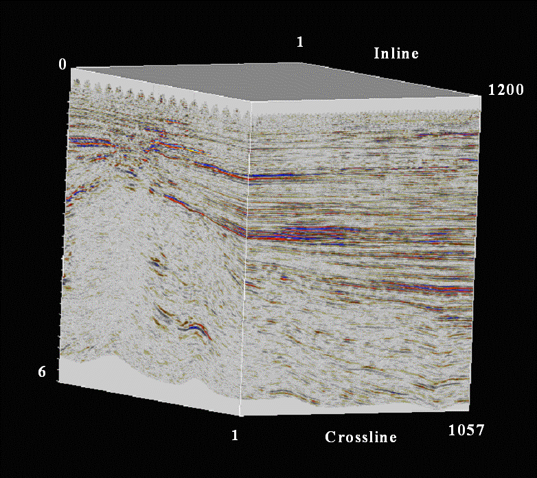
The figure below is an example of processed seismic cube that extends from 0 to 6 seconds and has inlines 1 to 1200 and crosslines 1 to 1057. The cube is displayed in a variable density display as opposed to the earlier variable area or wiggle trace displays.

Figure 35 3D seismic cube