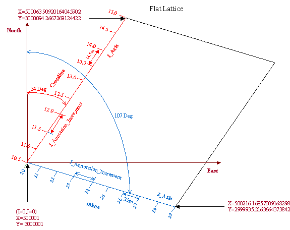
Since the sampling of the 3D cube is regular, it is not necessary to specify the location of each inline-crossline-time triplet. This can be accomplished by defining three-dimensional lattice, which can be decomposed into a two-dimensional lattice used to describe the inline-crossline locations in X and Y values on the surface, termed a flat lattice, with a third axis in time or depth to describe the sampling in the z direction. There are several methods that could be used to define a lattice, but the method chosen is to define the corner points. The figure is illustrates how this I done for the two-dimensional flat lattice.

Figure 36 Lattice example
The I and J axes for the lattice always begin at 0 and increase monotonically and the number of units that the lattice extends in the I and J directions is also specified to give the extent of the lattice. The first corner point, where I and J both equal 0, is called Point_0_0. The second corner point, where I is maximum and J=0, is named Point_I_0. Similarly the third point used where J is maximum and I=0 is named Point_0_J. The inline and crossline directions are assigned to one of the axis by means of description attributes. The inline and crossline numbers are then treated as annotation on the appropriate axes by specifying the inline and crossline number corresponding to Point_0_0 and the increment by which the annotation changes for one unit of change on the I or J axis. The values of the attributes used to define the lattice above are given in the table below.
|
Point_0_0_Position.Original_X_Longitude |
500,001 |
|
Point_0_0_Position.Original_Y_Longitude |
3,000,001 |
|
Point_I_0_Position.Original_X_Longitude |
500063.90920164045902 |
|
Point_I_0_Position.Original_Y_Longitude |
3000094.2667269124422 |
|
Point_0_J_Position.Original_X_Longitude |
500216.16857009168298 |
|
Point_0_J_Position.Original_Y_Longitude |
2999935.2163664373842 |
|
I_Axis_Description |
Crossline |
|
|
|
|
I_Count |
10 |
|
I_Annotation_At_0_0 |
10.5 |
|
I_Annotation_Increment |
0.5 |
|
J_Axis_Description |
Inline |
|
J_Count |
10 |
|
J_Annotation_At_0_0 |
20 |
|
J_Annotation_Increment |
1 |
To extend the lattice include a third dimension of depth or time a third axis, the K axis, is used. The attributes used correspond to those used for the I and J axes with the exception that the axis description is not given and is derived from the depth or time unit. To define a cube lattice that extended from 0 to 6 seconds with samples every 2 ms with the surface geometry given above the additional attributes in the table below must be specified.
|
K_Count |
3001 |
|
K_Annotation_At_0_0 |
0 |
|
K_Annotation_Increment |
2 |