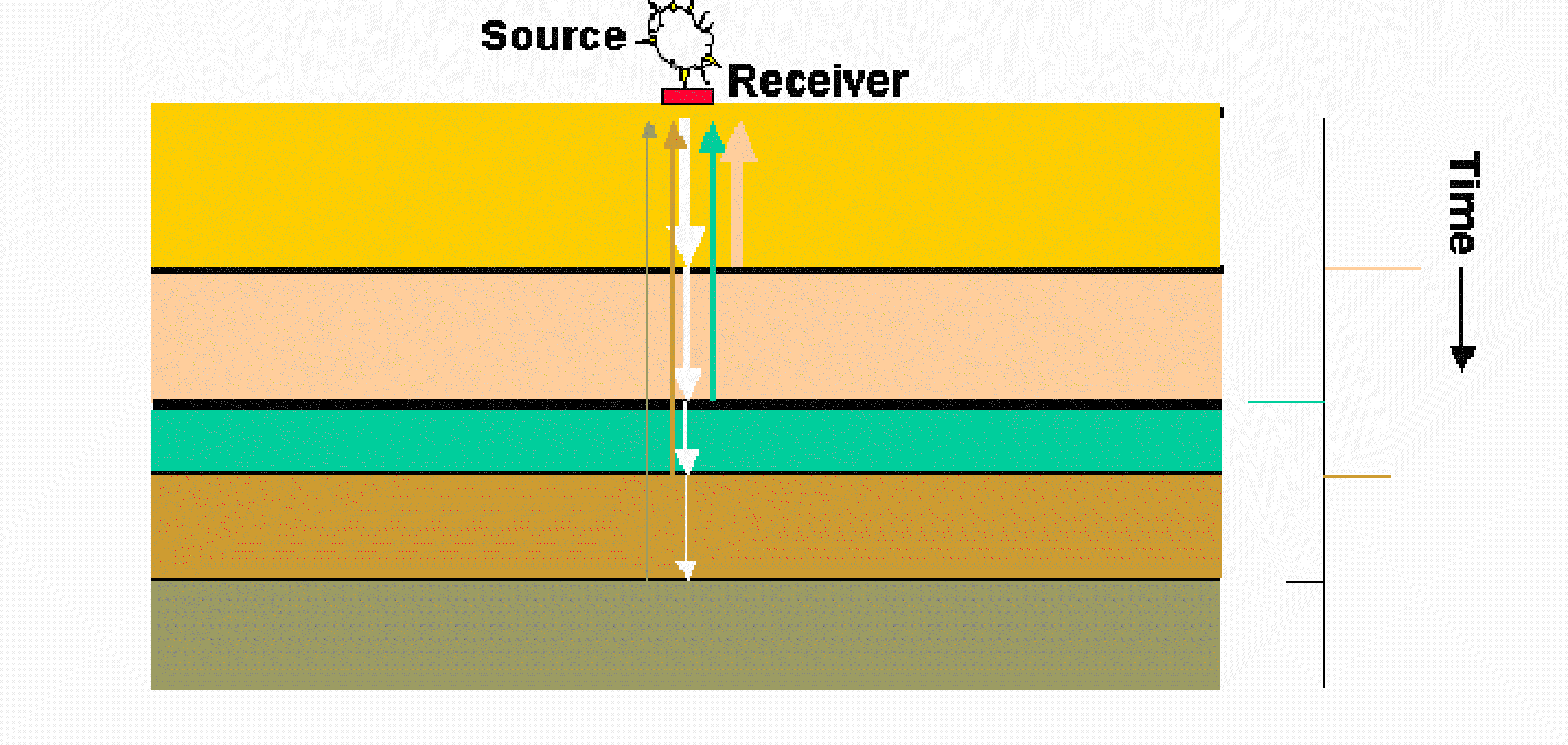
An idealized illustration of seismic reflection is shown in the figure below.

Figure 6 Idealized Zero Offset Single Source and Receiver
In this figure there are single source and single receiver in a zero offset configuration, that is, there they occupy the same location, and the rock layers are horizontal. The source generates a spike of sound energy that travels down through the layers. At each interface between layers some of the energy is reflected back to the surface because of a contrast in acoustic impedance of the material in the layers, where acoustic impedance is given as the product of the density and acoustic velocity of the material. Some of the energy continues to move downward through the next and where a portion is again reflected back to the surface. The energy reflected at each interface travels back to the surface where is acquired by the receiver. The trace at the right shows is the composite signal of all the returning reflected signals, given as a function of time it takes for the signal to travel to the interface and return to the receiver.